Wireless DetonatorBy: Spatula Tzar |
Wireless detonators are wonderful. They allow a great distance to be placed between a user and their device without even the need to run wires. Most amateur remotes however have a fatal flaw: stray radio waves can potentially trigger the device prematurely. My design completely eliminates accidental activation through the use of a security code.
 |
To start, you need a radio transmitter and receiver. No expensive device need be bought. You probably already have it. A standard cordless telephone works perfectly. It even has a built in keypad. Newer sophisticated phones might not work unless connected to a phone line, but older models usually work without problems. The phone need not be modified, but I chose to paint mine yellow with electrical tape stripes for sheer awesomeness. |
 |
This is the circuit I designed. (Click for the full image.) The phone line is fed into the 8870 DTMF decoder where any keypresses are converted to four parallel data lines. These lines are read by the PIC16F84 microcontroller where all the dirty work is done. Once the code is validated, the PIC activates a 15 amp relay, closing the circuit for one or more electrical igniters. Close observers may notice the switch is breaking the negative terminal of the battery instead of the customary positive. There is a very good reason for this. If the cathode of an alkaline battery is connected to a large conductor for long periods of time, galvanic corrosion develops. This is why the anode of cylindrical batteries has several times the surface area of the cathode. It wont make much of a difference in this small circuit, but it's good practice. |
 |
Here's my prototype circuit, planned out on a solderless breadboard. The LEDs were used for debugging the microcontroller program, and have no use in the final circuit. If you're having trouble finding the 8870 chip, look inside old answering machines. It's used when checking your messages from a remote location. |
 |
The program is fairly simple. It takes the data lines from the DTMF decoder, and stores each keypress in memory. When the # key is pressed, it compares the numbers to the programmed security code. If they match, it sets a pin high, activating the relay for two seconds. If the code is invalid, it resets. If it is ever idle for more than three seconds, it resets. A one second wait at the beginning prevents false readings from the decoder chip. Here is the source code: Programming PIC microcontrollers is beyond the scope of this writeup, but you might want to try this site to familiarize yourself with the basics. |
 |
Now we can begin constructing the container. I chose to build the circuit inside an Altoids tin (wintergreen flavour). After cutting holes for the switch and connectors, I soldered a pair of bolts to the bottom of the tin. They will serve to hold the circuit board in place. The inside is then lined with electrical tape to prevent short circuits. |
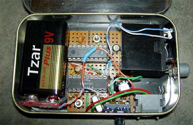 |
It was a tight fit, but I managed to cram everything inside the tin. I had to cut off the top of the tall LM7805 voltage regulator in order to close the lid, but is doesn't draw much power, so there is no need to worry about heat dissipation. Yes, that is an RCA socket connected to the relay. It was the only connector I could find capable of handling large currents. The 9V battery connector is actually made from a dead 9V battery. Pretty shrewd, huh? |
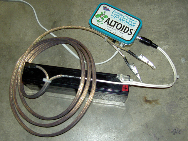 |
This is my igniter setup. The lead acid battery is switched by the relay circuit, sourcing a large current through 14 gauge wire to a pair of alligator clips. This setup conveniently interfaces with my electrical igniters and squibs. |
I know this may be beyond the means of many of you, but I will try to provide help with construction. If there is enough interest, I may even start selling them.
Bitcoin: 1KEWmWK3Sn9ToEHxhXmoXax6ycNGgLMfLv